To demonstrate the colours of the rainbow, I wanted to knock up a quick Arduino project that allowed any colour of the rainbow to be selected.
The user input was simply a potentiometer, and the output was to be three LEDs – a red, green and blue.
Working out how to map the potentiometer value (0 to 1023) onto brightnesses for each of the three LEDs was the main task. Looking around, there is a common algorithm listed here:
http://en.wikipedia.org/wiki/HSL_and_HSV
This algorithm turns values of hue, saturation and brightness into RGB intensities. Many Arduino projects implement this algorithm, an example of which can be found here:
http://eduardofv.com/read_post/179-Arduino-RGB-LED-HSV-Color-Wheel-
Without exception, all these projects implement a colour wheel. A colour wheel pulls in (on full saturation) any combination of any two primary colours. So it starts off with 100% red, then fades into 100% green (with yellow produced en-route) which then fades into 100% blue (with cyan on the way). It then fades back into 100% red, visiting magenta half-way between red and blue.
But hold on – the rainbow does not contain magenta. It may be a nice colour for mood lighting, but to show the colours of the rainbow, it just would not do.
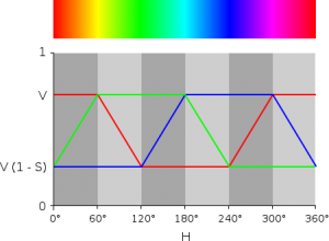
The following diagram from Wikipedia shows how the colour wheel hue maps onto the RGB intensities. The function listed in the above project takes a value for the hue between 0 and 255, with 0 being red on the left of the colour wheel bar, and 255 being the red on the far right.
 Being a wheel, the bar above wraps around – the red at each end is the same colour. Rainbows don’t wrap like this – red is at one end, and blue is at the other end. This range covers 240° of the colour wheel as seen above.
Here is the unit running in colour wheel mode. The full cycle starts and ends on red:
So, with a hue in the colour wheel being represented in the range 0 to 255, or 0° to 360°, if we are to reduce the range to 0°-240°, then this would be represented by a range of 0 to 170 in the algorithm.
So in the Arduino project, a potentiometer range of 0-1023 is converted to a hue range of 0-170. Turning the potentiometer through its full range then gives a colour output covering the full range of the colours of a rainbow.
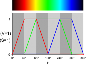
However, there is another twist. The rainbow does not stop at red and blue at each end. It carries on through infra-red and ultra-violet, neither of which we can see. So to demonstrate the colour range of a rainbow fully, we need to start at total darkness at both ends of the scale, fading up into red at one end, and fading from blue to darkness at the other end.
So this is what I am aiming for. The saturation (S) is set to 100%, as is the brightness (V). These are two settings that would affect the output as a whole. A saturation of less than 100% would “bleed” other colours through, which a rainbow would never do. A brightness of less than 100% would not be useful here – it would be like looking at a rainbow with a pair of neutral sub-glasses on: it would still be a rainbow.
We can do this using the brightness parameter of the HSV-to-RGB converter, rather than messing around with its innards. That way we can easily switch between colour wheel and rainbow to show how they differ.
Here is the unit running in rainbow mode (with Pin 12 set to HIGH). It starts and ends dark, emulating IR and UV:
Here is the code so far, which is work-in-progress. You can switch between colour-wheel and rainbow modes by setting pin 12 to either 0V or +5V.
/*
 Rainbow

 Take a tricolour LED through the colours of the rainbow using an analogue input.

 The circuit:
 * TBC

 Created 21 April 2012
 By Jason Judge

 This example code is in the public domain.

 */

// The three primary colour LEDs, driven as analgue outputs (actually PWM, but
// close enough for our analogue eyes).

const int ledPinRed = 11;    // Red LED connected to analogue out pin
const int ledPinGrn = 10;    // Green LED connected to analogue out pin
const int ledPinBlu = 9;     // Blue LED connected to analogue out pin

const int modeSwitchPin = 12;

// The Hue potentiometer goes on an analogue pin, taking the pin from
// 0V to 5V.

const int potPinHue = 0;

// Constants to define the ranges.

const int hueRedLow = 0;
const int hueRedHigh = 255;
const int hueBlue = 170;

// The size of the angle of one sector (1/6 of a colour wheel), and of a complete
// cycle of the colour wheel.

const int angleMin = 0;
const int angleSector = 60;
const int angleMax = 360;

const int brightMin = 0;
const int brightMax = 255;

// Work variables.

// The potentiometer value is mapped to the range 0 to 360 (degrees).
int potValueHue;

// The hue is the range 0 (red) to 170 (blue) in rainbow
// mode or 255 (red) in colour wheel mode.
// The brightness ranges from 0 (dark) to 255 (full brightness)

int hue, brightness;

// The saturation is fixed at 255 (full) to remove blead-through of different
// colours.
// It could be linked to another potentiometer if a demonstration of hue
// is desired.

const int saturation = 255;

// The brightess of each LED (0 to 255).

unsigned int r, g, b;

void setup()  {
    // Still need to set a baud rate, even for USB.
    Serial.begin(9600);

    // Set LED pins to output.
    pinMode(ledPinRed, OUTPUT);
    pinMode(ledPinGrn, OUTPUT);
    pinMode(ledPinBlu, OUTPUT);

    // Poteniometer analogue pin is an input.
    pinMode(potPinHue, INPUT);

    // TODO: mode switch in a digital input.
    pinMode(modeSwitchPin, INPUT);
}

void loop()  {
    // The Hue potentiometer value is mapped to degrees - 0 to 360 - for convenience.
    potValueHue = map(analogRead(potPinHue), 0, 1023, 0, 360);

    // Control the mode using a physical switch.

    if (digitalRead(modeSwitchPin)) {
        // Rainbow colour mode (infra-red to ultra-violet - well invisible to invisible ;-).

        // The hue ranges from red (0) at 60 degrees to blue (170) at 300 degrees.
        hue = constrain(map(potValueHue, angleSector, angleMax - angleSector, hueRedLow, hueBlue), hueRedLow, hueBlue);

        // Brightness - fade up 0-60 degrees
        brightness = constrain(map(potValueHue, angleMin, angleSector, brightMin, brightMax), brightMin, brightMax);

        // Brightness fade down 300-360 degrees
        brightness = brightness - constrain(map(potValueHue, angleMax - angleSector, angleMax, brightMin, brightMax), brightMin, brightMax);
    } else {
        // Colour wheel mode (red to red, wrapped around in a cycle).

        hue = map(potValueHue, angleMin, angleMax, hueRedLow, hueRedHigh);

        // The brightness is fixed at full for the colour wheel. This could be
        // linked to another poteniometer if that is a concept you wish to
        // demonstrate.
        brightness = 255;
    }

    // Do the conversion.
    HSBToRGB(hue, saturation, brightness, &r, &g, &b);

    analogWrite(ledPinRed, r);
    analogWrite(ledPinGrn, g);
    analogWrite(ledPinBlu, b);

    Serial.print(" bright=");
    Serial.print(brightness);
    Serial.print(" hue=");
    Serial.print(hue);
    Serial.print(" red=");
    Serial.print(r);
    Serial.print(" green=");
    Serial.print(g);
    Serial.print(" blue=");
    Serial.print(b);
    Serial.println("");
    delay(50);
}

// This function taken from here:
// http://eduardofv.com/read_post/179-Arduino-RGB-LED-HSV-Color-Wheel-

void HSBToRGB(
    unsigned int inHue, unsigned int inSaturation, unsigned int inBrightness,
    unsigned int *oR, unsigned int *oG, unsigned int *oB )
{
    if (inSaturation == 0)
    {
        // achromatic (grey)
        *oR = *oG = *oB = inBrightness;
    }
    else
    {
        unsigned int scaledHue = (inHue * 6);
        unsigned int sector = scaledHue >> 8; // sector 0 to 5 around the color wheel
        unsigned int offsetInSector = scaledHue - (sector << 8);	// position within the sector         unsigned int p = (inBrightness * ( 255 - inSaturation )) >> 8;
        unsigned int q = (inBrightness * ( 255 - ((inSaturation * offsetInSector) >> 8) )) >> 8;
        unsigned int t = (inBrightness * ( 255 - ((inSaturation * ( 255 - offsetInSector )) >> 8) )) >> 8;

        switch( sector ) {
        case 0:
            *oR = inBrightness;
            *oG = t;
            *oB = p;
            break;
        case 1:
            *oR = q;
            *oG = inBrightness;
            *oB = p;
            break;
        case 2:
            *oR = p;
            *oG = inBrightness;
            *oB = t;
            break;
        case 3:
            *oR = p;
            *oG = q;
            *oB = inBrightness;
            break;
        case 4:
            *oR = t;
            *oG = p;
            *oB = inBrightness;
            break;
        default:    // case 5:
            *oR = inBrightness;
            *oG = p;
            *oB = q;
            break;
        }
    }
}


Thanks,
I know you wrote this a while ago, but this is just what I wanted.
The SparkFun guide starts with an LED, then uses a potentiometer to control it. It then “improves” the example by going to an RGB LED, but removing the potentiometer. Sure seems like they are moving backwards. This was the next logical step and a lot of fun.
Cheers
I don’t think Sparkfun was moving backwards in the SIK guide. They teach you individual concepts like reading Analog values and using PWM.
Once you have mastered and understand these concepts you can combine this knowledge to create more complex useful projects.
The most fun I had was combing everything learned from the projects in the SIK guide.
I tried to compile this code in Arduino UNO and when I tried the error reads, “exit status 1
‘HSBToRGB’ was not declared in this scope”
Can you help?
I’ve not used this for a while, but I’m just wondering if it is the order of the functions that is the problem? Try moving function `void HSBToRGB(…)` to above function `loop(…)`, so that they are defined in the order in which they are used.
Hi, Some word processor had inserted a lot of weird formatting:
>> became > became ampersand gt semicolon (JJ: fixed:-)
etc etc
I have it compiling but not tested yet.
See it here:
http://arduino-info.wikispaces.com/MaryAlice-ColorWheel-RGB
Regards, MaryAlice Osborne
…In The Woods in Vermont, USA
maryalice@yourduino.com
Thank you. I keep being reminded by things like this, how appalling the handling of HTML entities in WordPress is. It converts back and forth so many times, in seemingly random layers in the platform. No consistency at all. Hopefully it is fixed now, unless I edit the page again with the visual editor on.
> became ampersand gt semicolon
Yes, it’s annoying, and it is a problem with the way WordPress has always worked, doing conversions between special characters and HTML entities inconsistently and multiple times at all sorts of inappropriate levels. I can’t seem to see an easy way to fix this one, so best just be aware! Thanks.